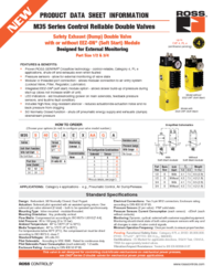
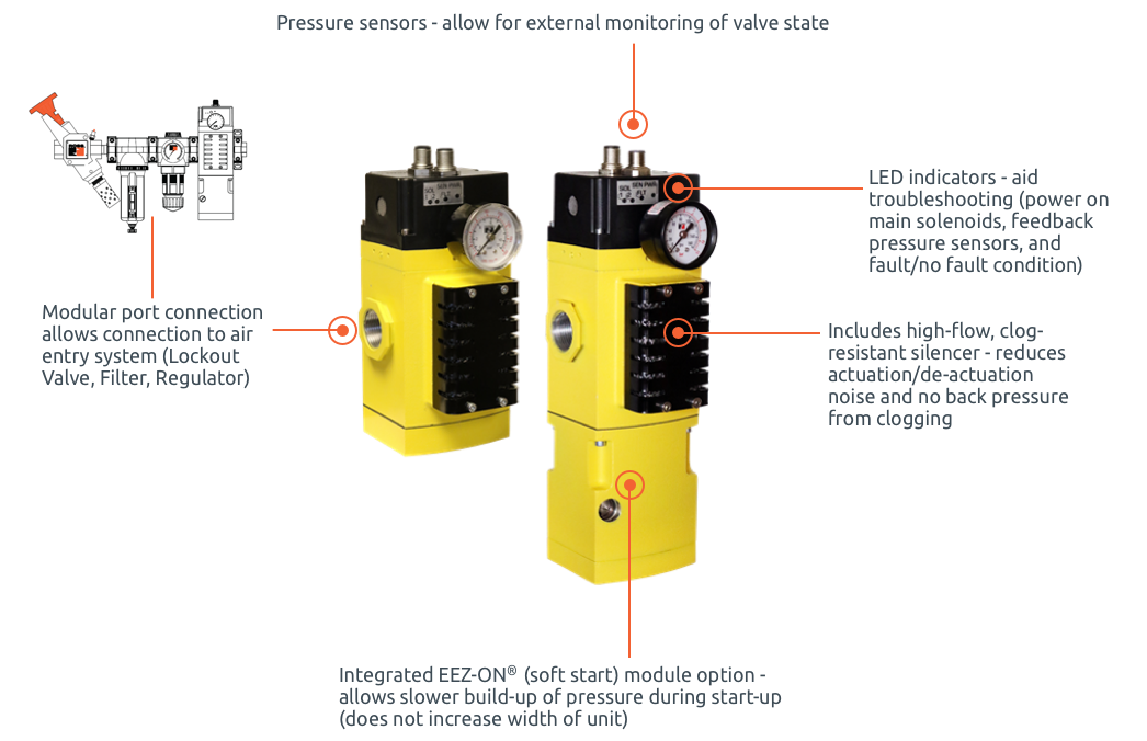
Proven ROSS SERPAR® Crossflow technology – control-reliable, Category 4, PL e applications, shuts-off and exhausts even when faulted – Safety Exhaust (Dump) Valve
Port Size 1/2 & 3/4

Proven ROSS SERPAR® Crossflow technology – control-reliable, Category 4, PL e applications, shuts-off and exhausts even when faulted – Safety Exhaust (Dump) Valve
Port Size 1/2 & 3/4
M35 Series Safety Exhaust Dump Valve Operation Overview
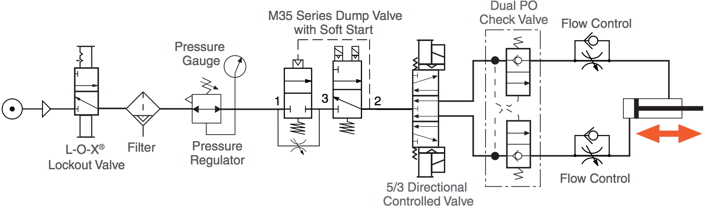
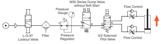
Ross Controls has introduced its new M35 Series Safety Exhaust Dump Valve with or without soft start for Category-4, PL e machine guarding applications.
The M35 Series valve is designed to supply air to a zone or entire machine/system until signalled to shut off and exhaust residual downstream pneumatic energy from the machine. Thus, reducing the hazards associated with the presence of residual energy during employee access and/or minor servicing. The safety function of the M35 Series valve is to shut off supply of pneumatic energy and to exhaust any pneumatic energy from downstream of the valve. Note that the M35 series valve cannot exhaust pneumatic energy from downstream of obstructions such as check valves and closed centre function valves.
Conditions at Start:
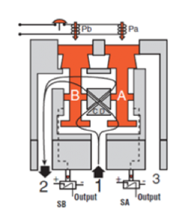
Normal Operation:
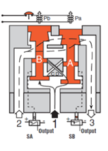
Completion of Normal Cycle:
Detecting a Malfunction:
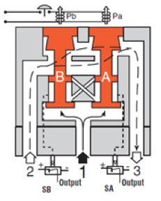
Design: Redundant, 3/2 Normally Closed, Dual Poppet.
Actuation: Solenoid pilot operated with air assisted spring return. One solenoid per valve element (2 total) – both to be operated synchronously.
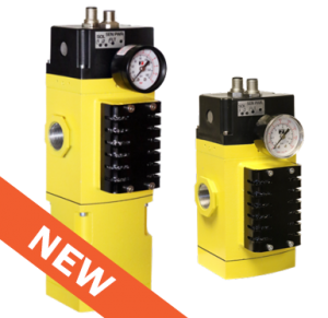
Mounting Type: Inline mounted – modular/threaded.
Mounting Orientation: Any, preferably vertical.
Flow Media: Compressed air according to ISO 8573-1:2010 [7:4:4].
Inlet Pressure: 30 to 150 psig (2 to 10 bar).
Ambient Temperature: 40° to 120°F (4° to 50°C).
Media Temperature: 40° to 175°F (4° to 80°C). For temperatures below 40°F (4°C), the compressed air must be dried according to ISO 8573-3, class 7.
Standard Voltages: 24 volts DC.
Pilot Solenoids: According to VDE 0580. Rated for continuous duty.
Pilot Solenoids Power Consumption (each solenoid): 1.2 watts.
Enclosure Rating: According to DIN 400 50 IP 65.
Electrical Connections: Two 5-pin M12 connectors. Enclosure rating according to DIN 400 50 IP 65.
Pressure Sensors (2 per valve): Solid state.
Pressure Sensors Current Consumption (each sensor):< 23mA (each without contacts).
Monitoring:Dynamic, cyclical, external with customer supplied equipment. Monitoring should check state of both valve pressure sensors with any and all changes in state of valve control signals.
Minimum Operation Frequency: Once per month, to ensure proper function.
Functional Safety Data: Pending.